|
|
|
|
|
|
|
|
|
| RUP-15 |
|
|
|
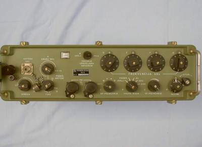
RUP-15
The RUP-15 is a very good radio for radio amateurs, however it has a few drawbacks. Roland Myers, G8LUL is an admirer of this radio and has tried to make it as perfect as possible by providing: 1) modifications and 2) enhanced schematics: 1) The RUP-15 /PD-8 is very high class equipment. It has LSB, CW and AM mode, so it seems just right for ham radio. The audio, however, is absolutely awful when the original carbon mike is used! Also, most of these radios have incorrectly adjusted RF PA bias. This makes it sound so bad on Transmit that you are sorry you bought it! You can read my article which describes how to overcome these problems by modifying the handset and adjusting the PA bias.. The modifications come as a .pdf- file; you can read or copy it by following this link: 2) The initial copies of the schematics were taken from the original handbook, and were not easy to read. I have enhanced the circuit diagrams and included a file to explain the changes. The description as an rtf- file; you can read or copy it by following this link: How the circuits were enhanced The Schematics can be downloaded as a .zip- file; size is 5.4 mb: Download schematics as .zip Some infos about the operation, also from Roland Myers, G8LUL: THE PD-8 FRONT PANEL: THE AUDIO GAIN SELECTOR: The PD-8 has an AUDIO GAIN SWITCH rather than a potentiometer. This allows the AF GAIN SWITCH to also provide switching positions to control the lights and to allow the TUNE METER to indicate the supply voltage being applied to the equipment. These are the switch functions: 1 = Medium Audio Gain, Lights ON, meter indicates supply voltage 2 = Minimum Audio Gain, Lights ON, meter indicates RF TUNE for transmit 3 = Medium Audio Gain, Lights OFF, meter indicates RF TUNE for transmit 4 = Intermediate Audio Gain, Lights OFF, meter indicates RF TUNE for transmit 5 = Maximum Audio Gain, Lights OFF, meter indicates RF TUNE for transmit THE RF GAIN CONTROL and AGC SYSTEM: The PD-8 offers excellent AGC in LSB and AM modes, the RF GAIN control should be set to maximum to give full authority to the AGC system. You may reduce the RF GAIN setting to limit the maximum gain if desired. Note that, when switched to CW MODE, there is NO AGC - and you MUST control the RF GAIN manually to avoid overloading the front-end of the receiver. Remember to reduce the RF GAIN fully before switching to CW (A1) - then increase as required. TUNING THE TRANSMITTER: To avoid switching high RF energy with the INDUCTOR SWITCHES, it is best to find an approximate aerial-match by listening to the receiver for best signal when switched to A1 (CW) mode. This mode is selected to prevent the AGC from masking the result you are listening for. 1 Set the two lower left controls (CAPACITOR and INDUCTOR SMALL) to "north" 2 Switch to A1 (CW) and reduce the RF GAIN until you can JUST hear signals or noise 3 Rotate the INDUCTOR LARGE switch for maximum signal or noise, reducing RF GAIN if necessary 4 Now switch the MODE SWITCH to TUNE and adjust CAPACITOR and INDUCTOR SMALL for maximum TUNE METER The TUNE METER will normally give approximately half-scale deflection The PA is protected against OPEN CIRCUIT or SHORT CIRCUIT RF OUTPUT - but it is wise to use good technique to avoid proving that the protection system is working! THE FINE FREQUENCY CONTROL: This control should normally be set to OFF by turning the knob fully anti-clockwise. When in this position, a micro-switch is activated which takes the fine-frequency variable capacitor out of circuit. This ensures the best accuracy of the synthesiser. The control can be used to interpolate between the exact 1kHz steps of the synthesiser. It tunes a very low frequency free-running oscillator which is mixed into the synthesiser oscillator system to allow for stations which have a slight frequency error. Drift with temperature change is negligible. Please note that this control shifts the frequency of both TRANSMIT and RECEIVE by up to +/- 500Hz. There is a MECHANICAL LOCK on the FINE FREQUENCY CONTROL to ensure that any selected frequency shift can be held securely.
Technical data:
|
)
