|
|
|
|
|
|
|
|
|
| SCR-585- A / SCR-585-B |
|
|
|
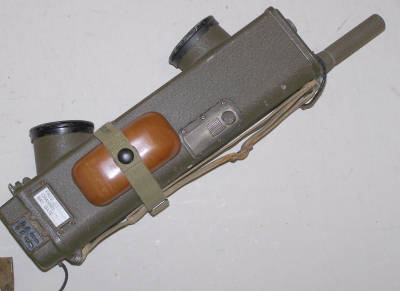
SCR-585- A / SCR-585-B PTT- is operated by means of a Control Shaft (MC-355 or MC-365-B), The control shaft is different due to glider type. For use in a glider two headsets are connected (for pilot and co-pilot), but only one throat microphone. If you look at the photos of the BC-721, you see that on one side of the radio there is the PTT switch, above that there is a small sliding door, and in the cover, there is a "Jones" connector to bring in glider audio and glider power. The radio fits into the mounting with this side down. The sliding door needs to be open, and you see in the bottom of the mounting a pin that goes into a hole behind the sliding door. This pin presses on a recessed switch which disconnects the BC-721 telescoping antenna from the electronics, and connects the glider antenna (which goes to the pin you see) to the electronics in the BC-721. By pulling on the PTT knob, you make a mechanism push the radio's PTT switch.
The "Jones" - connector at the bottom of the radio connects the radio and provides audio and power from the glider; by the " Radio Control Box BC-722-B". It contains :
So you have * external antenna connection to the radio behind the sliding door, * external power to the plug in the radio's bottom cover, and * a squeeze mechanism for Push-to-talk. After opening a lock and a belt, you can take out the radio. It now can be used as a stand alone radio, can be switched on by pulling out the antenna, like the BC-611. Volume control then is not longer possible.
Also see the article by Alan Tasker : "U.S. Military Portable Radios"
Technical data :
|
)
)
)
)
)
